
💡 Key Decision Factors
- Match Frequency & Impedance – Prevent signal degradation from the start
- Prioritize Environmental Durability – Ensure reliability in harsh conditions/li>
- Balance Size vs Performance – Optimize for space-constrained applications
The Connector’s Critical Role in Modern RF Systems
Most engineers discover the importance of RF connectors the hard way – during final validation when a poorly chosen connector causes unexpected signal degradation. Unlike other components that can be tuned or compensated, connectors represent a fixed point of failure that can undermine your entire design.
We’ve seen 5G small cells fail certification due to connector-induced PIM, automotive radar systems develop intermittent faults from vibration, and IoT devices suffer range reduction from impedance mismatches. The connector choice ultimately determines whether your design performs reliably in the field or becomes a service nightmare.
Three Non-Negotiable Electrical Parameters
Frequency Range: Your First Design Gate
Every connector has a fundamental frequency limit where higher-order modes degrade performance. This isn’t theoretical – we’ve measured 3dB additional loss in SMA connectors operating just 2GHz beyond their rated limit.
Practical Frequency Guidelines:
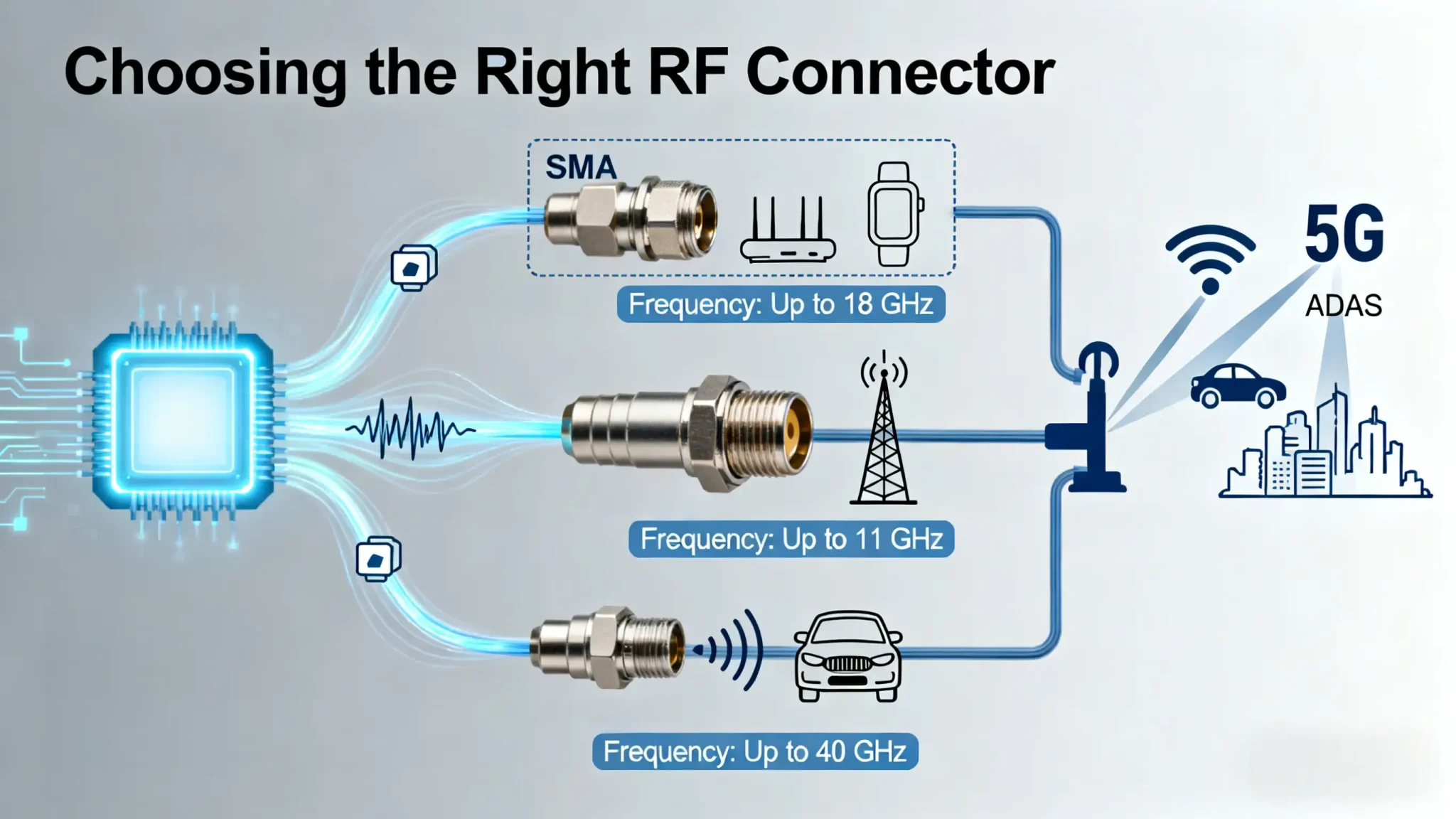
Standard commercial (SMA, MCX): DC-18GHz for cost-sensitive applications
Precision interfaces (2.92mm, 2.4mm): DC-40GHz for 5G mmWave and advanced radar
Miniature commercial (SMP, SMPM): DC-40GHz for space-constrained designs
Engineering Reality Check: “We specify connectors with 25% frequency margin over our operating band. The slight cost increase prevents expensive re-spins when requirements evolve.”
Impedance Consistency: The Silent Signal Killer
While everyone specifies 50-ohm systems, few verify impedance consistency across the entire signal path. The connector interface often becomes the discontinuity point, particularly in automotive radar applications where even minor reflections create false targets.
Critical Verification Points:
Connector interface to PCB transition
Cable assembly to connector junction
Mating surface contact integrity
Power Handling: Beyond Datasheet Numbers
Datasheet power ratings assume ideal conditions, but real-world deployments introduce variables that derate performance. Automotive radar systems, for instance, experience temperature extremes that reduce power handling by 30-40% compared to lab specifications.
| Connector Series | Frequency Range | VSWR Typical | Mating Cycles | Cost Tier |
|---|---|---|---|---|
| SMA | DC-18 GHz | 1.25:1 @ 12 GHz | 500 | Low |
| 2.92mm | DC-40 GHz | 1.20:1 @ 26 GHz | 5,000+ | High |
| SMP | DC-40 GHz | 1.30:1 @ 40 GHz | 100-500 | Medium |
| MCX/MMCX | DC-6 GHz | 1.25:1 @ 4 GHz | 1,000+ | Low |
The Workhorse: SMA and Precision Variants
SMA connectors dominate test equipment and commercial systems, but their threaded interface becomes problematic in high-vibration environments. The precision 2.92mm variants offer superior performance but at a significant cost premium.
When to Choose SMA:
Laboratory and development environments
Cost-driven commercial applications below 12GHz
Systems with minimal mating cycle requirements
Miniature Solutions: SMP and Micro Connectors
The push toward miniaturization makes SMP connectors essential for modern compact designs. Their blind-mate capability simplifies assembly in dense arrays, though mating cycle limitations require careful consideration for field-serviceable equipment.
Space-Constrained Applications:
5G massive MIMO antenna arrays
Automotive radar sensor modules
Portable test and measurement equipment
Robust Interfaces: N-Type and Automotive Specials
For infrastructure and harsh environments, threaded connectors like N-Type provide the reliability needed for 20-year service life. The automotive industry has developed specialized RF connectors with integrated sealing and vibration-resistant locking features.
Application-Specific Selection Guidelines
5G Infrastructure: Balancing Performance and Density
5G deployments demand unprecedented connector density while maintaining signal integrity across wide bandwidths. The transition to mmWave frequencies has made connector choice more critical than ever.
5G Connector Challenges:
Phase stability across temperature for beamforming
PIM performance for receiver sensitivity
Environmental sealing for outdoor deployments
Field Experience: “Our tower audits revealed that 40% of PIM issues originated from connector interfaces, not the antennas themselves. Proper connector selection eliminated 90% of these field problems.”
| Radar Type | Frequency Band | Key Challenges | Recommended Connectors |
|---|---|---|---|
| Long-Range | 76-77 GHz | Signal integrity, phase stability | 2.92mm, SMA with lock |
| Short-Range | 24-25 GHz | Size constraints, cost | SMP, SMPM |
| In-Cabin | 60-64 GHz | Miniaturization, reliability | SMPM, MMCX |
Automotive environments represent the ultimate reliability challenge. Temperature cycling from -40°C to +125°C, constant vibration, and chemical exposure eliminate all but the most robust connector solutions.
Automotive Validation Requirements:
Vibration testing to 20G across frequency spectrum
Thermal shock cycling (500+ cycles)
Salt spray and chemical resistance validation
IoT Devices: The Miniaturization Battle
IoT designs face the opposite challenge – achieving reliable RF performance in the smallest possible form factor at the lowest cost. This often means sacrificing serviceability for size and price.
IoT Design Trade-offs:
U.FL connectors for permanent assembly (1-5 mating cycles)
MCX for limited service access (100-500 cycles)
MMCX for test points and modular designs (500+ cycles)
The Complete Selection Checklist
Environmental Validation
Don’t trust datasheet specifications alone. We recommend:
Testing 3 vendor samples across your temperature range
Validating VSWR under vibration (not just static conditions)
Verifying mating force consistency across 100+ cycles
💡 Practical Tip:
Manufacturing Reality: “A $0.50 connector that requires 5 minutes of skilled labor to install costs more than a $3.00 connector that snaps into place automatically. Always calculate total installed cost.”
Reliability and Service Life
Mating cycle specifications assume perfect alignment and clean environments. Derate published specifications by 50% for field applications and by 30% for factory environments.
Conclusion
Selecting the right RF connector is a multifaceted engineering decision that balances electrical performance, mechanical robustness, environmental resilience, and cost. There is no universal “best” connector, only the optimal choice for a specific application. By systematically evaluating your requirements against the parameters discussed—from the mmWave demands of 5G and radar to the cost and size pressures of IoT—you can secure the critical links in your RF chain, ensuring your design delivers on its promise of reliability and high performance.
Need Expert Guidance on Your Specific RF Connector Challenge?
Our engineering team specializes in solving complex interconnect problems for 5G, Automotive, and IoT. Contact us today for a personalized component recommendation and free samples.
Email Our Sales Team