
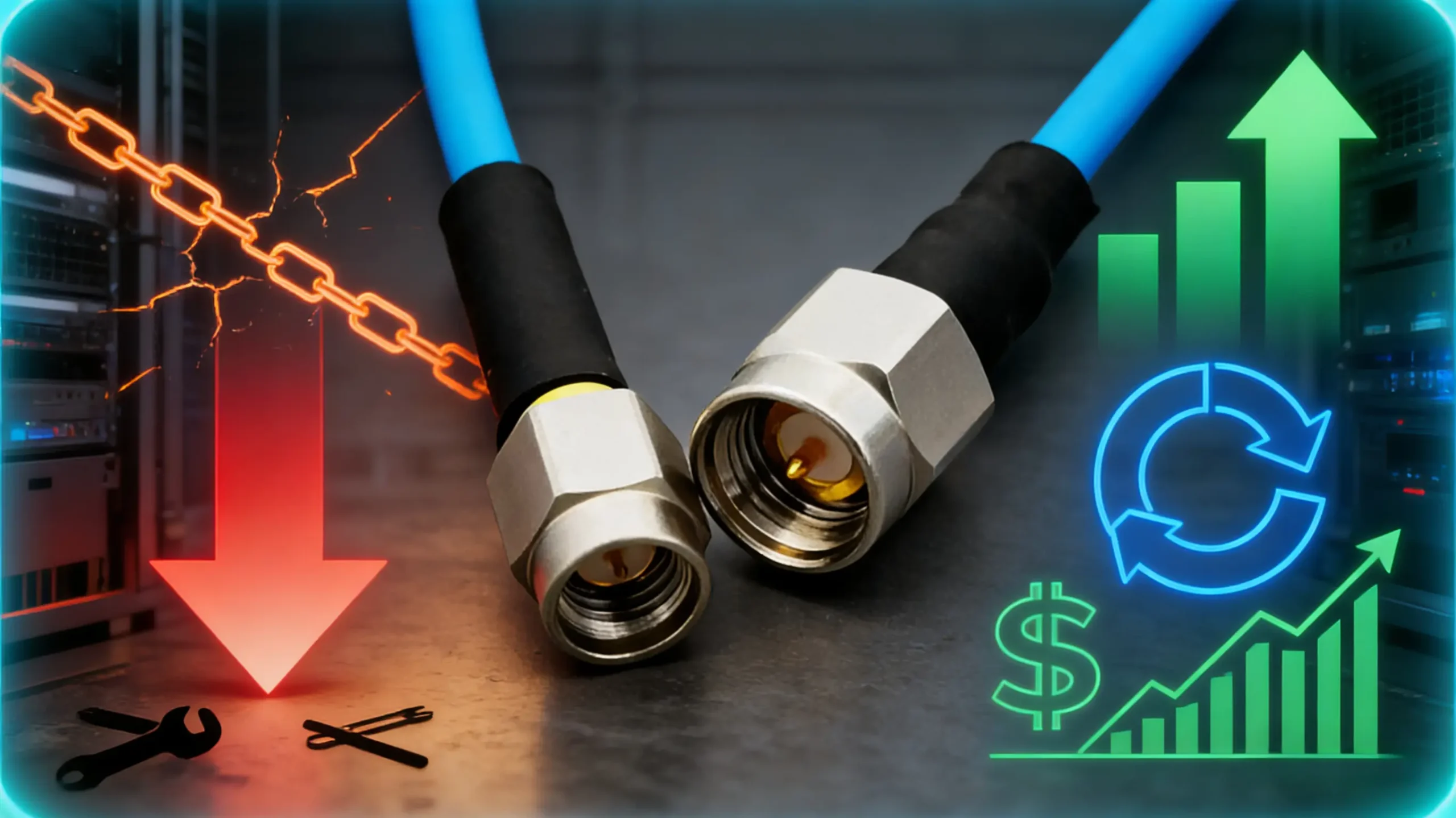
💰 Key Points Summary
The Hidden Economics of RF Cable Failure
In facility management and system design, RF cables are frequently treated as low-cost line items, selected primarily on initial purchase price and basic electrical specs. This approach creates a significant financial blind spot. Data aggregated from maintenance records across multiple industrial and telecom sites shows a consistent pattern: the cable assembly representing less than 2% of a system’s initial hardware cost can be responsible for over 15% of its annual operational expenses through unplanned downtime, technician labor, and collateral calibration costs.
The failure is rarely catastrophic. More often, it’s the gradual degradation of a durable cable assembly in a harsh environment—increasing VSWR that corrupts measurements, intermittent connections that cause test station false failures, or compromised shielding that introduces interference. These issues don’t trigger immediate replacement; they create chronic, expensive problems that are difficult to diagnose. Shifting the selection criteria from purchase price to total cost of ownership (TCO) is not an accounting exercise—it’s a strategic decision that directly impacts system reliability and bottom-line profitability.
Quantifying the True Cost of Cable Downtime
Labor, Recalibration, and Opportunity Costs
When a standard cable fails in the field, the immediate cost isn’t just the $50 replacement part. The true expense cascade includes:
Diagnostic Labor: 1-2 hours for a technician to identify the cable as the root cause.
Replacement Labor: 30-60 minutes to physically replace and reroute the cable.
System Recalibration: 1-4 hours to recalibrate the affected test station or measurement system.
Production/Data Loss: The value of lost output or missed data during the downtime.
In a cellular base station, a single dropped carrier due to a faulty jumper might cost hundreds of dollars in lost revenue per hour. In an automated test equipment (ATE) rack, downtime can exceed $1,000 per hour in lost device testing capacity. A ruggedized RF cable that prevents just one such incident per year can pay for its entire price premium.
Calculation Framework: Total Failure Cost = (Labor Hours × Hourly Rate) + (Recalibration Cost) + (Downtime Hours × Hourly Loss Rate). Apply this to your specific operational reality.
| Cost Factor | Typical Range (Industrial Setting) | Impact of Durable Cable | Standard Reference |
|---|---|---|---|
| Unplanned Downtime Cost | $500 – $5,000+ per hour | Reduces frequency and duration | ISO 14224:2016 (Equipment reliability) |
| Field Technician Labor Rate | $80 – $150 per hour (loaded) | Reduces service visits | Industry benchmark data |
| System Recalibration Labor | 1-4 hours @ $100-$200/hour | Extends calibration intervals | ISO/IEC 17025:2017 |
| Cable Replacement Frequency | 1-2 years (standard) vs. 3-5+ years (rugged) | 3-5x longer service life | IEC 61196-1 (Cable life test) |
💡 Financial Insight
When presenting a proposal for premium cables, don’t just compare unit prices. Create a 3-year TCO comparison spreadsheet that includes your estimated failure rates, labor costs, and downtime value. This shifts the conversation from procurement to operations and finance, where the value of reliability is truly understood.
How Ruggedized Design Extends Service Life
Mechanical Construction and Environmental Sealing
The longevity advantage of ruggedized RF cable assemblies stems from deliberate design choices that address specific failure mechanisms:
Strain Relief & Connector Attachment: Over 60% of field failures occur at the cable-connector interface due to flexing and strain. Rugged designs use extended, overmolded strain relief that distributes mechanical stress over a greater length of cable, preventing conductor breakage. The connector attachment often includes additional crimping or potting for environmental sealing.
Jacket and Shielding Materials: Standard PVC jackets degrade under UV exposure, extreme temperatures, and chemical contact. Rugged cables use specialized materials like polyurethane or fluoropolymers that resist abrasion, cutting, and environmental stress cracking. The shielding—often a combination of braid and foil—is denser and better bonded to maintain EMI/RFI integrity through flexing cycles.
Validation Approach: Look for cables tested to relevant standards: IP67/IP68 for ingress protection, UL/CSA for flame retardancy, and specific MIL-STD or IEC standards for flexing, crush resistance, and temperature cycling. The test report is more valuable than a marketing claim.
| Application Environment | Primary Failure Mode (Standard Cable) | Ruggedized Design Feature | Resulting Life Extension |
|---|---|---|---|
| Outdoor Cellular/Radio Site | UV degradation, moisture ingress, connector corrosion | UV-resistant jacket, IP67 sealed connectors | 3-4x (5+ years vs. 18 months) |
| Industrial Robot Arm | Conductor fatigue from continuous flexing | High-flex conductors, torsion-resistant design | 5-10x (Millions of cycles) |
| Automotive Test Bench | Crushing from equipment, vibration-induced connector loosening | Crush-resistant jacket, locking connectors (e.g., 7/16 DIN) | 3x (Matches vehicle test program duration) |
| Portable Military/Field Equipment | Physical abuse, extreme temperatures, sand/dust | Armored jacket, wide-temperature materials, MIL-SPEC construction | Essential for mission reliability (vs. frequent failure) |
What technical support do you provide for test modules integration?
admin2025-11-11T13:44:04+08:00We offer complete technical support throughout the integration process. Our engineering team provides detailed application guidance, performance optimization advice, and troubleshooting assistance to ensure successful implementation of your test modules in various testing environments.
What quality assurance measures do you implement for test modules?
admin2025-11-11T13:43:10+08:00Every test module undergoes comprehensive quality validation, including impedance matching verification, signal integrity analysis, and mechanical cycle life testing. This rigorous process ensures all delivered test modules meet our strict performance and reliability standards.
Can you customize test modules for specific testing requirements?
admin2025-11-11T13:42:02+08:00We specialize in developing custom test modules tailored to unique application needs. Our engineering team can modify probe configurations, interface types, and performance specifications to create bespoke solutions that address your specific device validation challenges.
What is the typical lead time for standard test modules?
admin2025-11-11T13:40:40+08:00For standard test modules configurations, our typical production lead time ranges from 2 to 3 weeks. This efficient turnaround applies even to single-unit orders, ensuring you receive your required test modules promptly to maintain your project development schedule.
What are the main application areas for your test modules?
admin2025-11-11T13:38:59+08:00Our comprehensive range of test modules serves diverse testing applications across multiple industries. These include semiconductor wafer validation, high-frequency RF component testing, and PCB in-circuit functional verification, providing reliable solutions from R&D labs to production floors.
What is the minimum order quantity for your test modules?
admin2025-11-11T13:30:57+08:00REECUFUTURE proudly supports a minimum order quantity of just 1 unit for all our test modules. This policy applies to both our standard catalog products and fully customized solutions, enabling us to serve prototyping and low-volume production needs effectively.
What industries and applications do your test probes typically serve?
admin2025-11-11T12:49:37+08:00Our test probes serve a diverse range of industries including semiconductor manufacturing for device validation and testing, automotive electronics for control system verification, consumer electronics for production testing, and industrial automation for quality control. They are also widely used in telecommunications equipment testing, medical device validation, and aerospace applications where reliable electrical contact and consistent performance are critical for success.
What materials and construction methods ensure the reliability of your test probes?
admin2025-11-11T12:47:49+08:00Our test probes feature gold-plated beryllium copper or steel plungers for optimal conductivity and wear resistance, precision-machined phosphor copper barrels for consistent alignment, and high-quality music wire springs for reliable mechanical action. This material selection, combined with advanced manufacturing processes, ensures excellent electrical performance, mechanical durability, and long-term reliability in demanding testing environments.
Implementing a Proactive Cable Management Strategy
From Reactive Replacement to Predictive Maintenance
Investing in durable cables is the first step; managing them proactively maximizes the return. Implement a simple but effective cable management and monitoring system:
Catalog and Label: Assign a unique ID to each critical cable assembly. Log its installation date, location, and expected service environment.
Schedule Inspections: For harsh environments, perform a visual and electrical inspection every 6-12 months. Check for jacket cracks, connector integrity, and measure insertion loss/VSWR against a baseline.
Monitor Performance Trends: In automated systems, monitor key RF parameters (e.g., reflected power) that can indicate degrading cable performance before complete failure.
This approach allows you to plan cable replacement during scheduled maintenance windows, avoiding unplanned downtime. It also generates valuable data to refine your future cable specifications and justify further investments in quality.
💡 Procurement Strategy
Work with suppliers who provide full test reports and who understand your application environment. The best partners will ask about your specific challenges (vibration frequency, temperature range, chemical exposure) and recommend or customize a solution, rather than just offering a standard catalog item. This consultation is part of the value of their “free design service.”
Calculating Your Specific Return on Investment (ROI)
Building a Compelling Business Case
To move beyond the technical department and secure budget for premium RF cable assemblies, you need a clear financial model. Here’s a simplified framework using conservative estimates:
Scenario: A manufacturing test station with a $200/hour downtime cost.
Standard Cable: Fails once per year, causing 4 hours of downtime + 2 hours of labor. Annual cost: (6 hours × $200) + $50 cable = $1,250.
Rugged Cable: $300 initial cost, fails once every 3 years. Annualized cost: ($300/3) + (6 hours × $200 / 3) = $100 + $400 = $500.
Annual Savings: $1,250 – $500 = $750 per station.
Payback Period: ($300 – $50) / $750 = 0.33 years (approx. 4 months).
This stark financial picture makes the case unequivocal. When scaled across multiple stations or systems, the savings become substantial.
💡 Sustainability Angle
Durable cables also contribute to sustainability goals by reducing electronic waste. One cable lasting 5 years generates less waste and has a lower lifetime carbon footprint than 2-3 standard cables requiring manufacturing, packaging, and shipping over the same period. This is an increasingly valuable point for corporate ESG (Environmental, Social, and Governance) reporting.
Request a Free Cable Lifecycle Cost Analysis for Your Application
Our engineers can help you analyze your specific operating environment and build a customized TCO model to justify investing in durable RF cable solutions. Contact us for a consultation.
Email Our Sales Team