
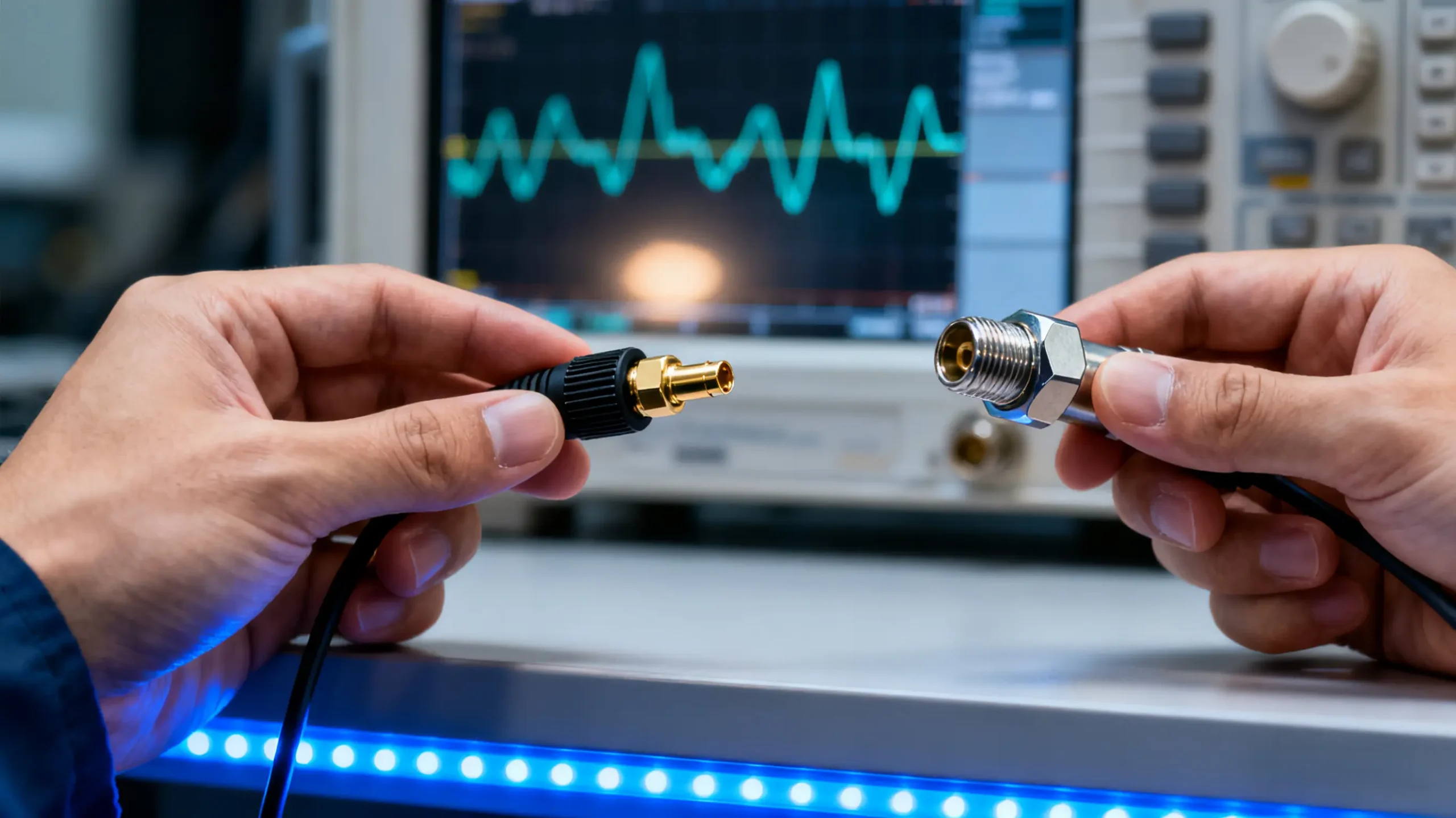
We’ve all been there. You’ve just spent the better part of a day collecting intricate S-parameter data, only to discover a nagging inconsistency that traces back to a seemingly minor oversight—the wrong RF probe or a mediocre connector. It’s a frustrating reminder that in our world of high-frequency electronics, the signal path is only as good as its weakest physical link. Choosing the right RF test probes and connectors isn’t just a box to check; it’s a fundamental engineering decision that separates reliable, repeatable results from costly and confusing dead-ends. Let’s break down this selection process into a practical, engineer-to-engineer discussion.
📝 Key Points Summary
More Than Just Metal: The Unsung Heroes of Your Signal Chain
It’s easy to get lost in the specs of your VNA and overlook the components you physically handle. But these interfaces are where the theoretical meets the tangible. They are the gatekeepers of your signal integrity.
RF Test Probes: The Delicate Art of Making Contact
RF Test Probes are the precision scalpels of the test world. They’re not just glorified pogo pins; they are finely tuned transmission lines designed to access those tiny, non-connectorized test points on your PCB. I see them most often in two key scenarios: in the R&D lab, where an engineer is painstakingly debugging a new power amplifier layout, and on the production floor, where a custom pogo pin fixture on an ATE system verifies a thousand smartphone boards per shift. The challenge here is balancing mechanical force to ensure a reliable electrical contact without damaging the delicate pad or component underneath. It’s a precision game.
RF Connectors: The Robust Backbone of Your Setup
If probes are the scalpels, RF Connectors are the durable pipes and valves of your test infrastructure. They’re built for the long haul, forming the semi-permanent connections between your cable assemblies and instruments. From my experience, this is where a “good enough” mentality can bite you. I’ve seen projects delayed because someone used a low-cost, non-name-brand SMA connector that failed after fifty mating cycles, its center pin retracting into the insulator. The connector you choose is a commitment to long-term reliability. Whether it’s the ubiquitous SMA or the more exotic 2.92mm, the goal is a connection you can trust, cycle after cycle.
💡 From the Bench: A Lesson on the “Weakest Link”
Early in my career, I watched a team chase a 2 dB noise figure discrepancy for a week. The culprit? A single, slightly out-of-spec adapter in a chain of otherwise flawless, high-performance components. It was a powerful lesson: your entire measurement is dictated by the worst component in your signal path. Always design and specify your interconnects as a cohesive, matched system.
The Five-Point Checklist: How to Choose with Confidence
Over the years, I’ve distilled the selection process down to five key questions. Answer these, and you’ll be 90% of the way to the right solution.
1. What’s Your Real Frequency?
This is your first and most non-negotiable filter. But a word of caution: just because a connector is rated for 18 GHz doesn’t mean it performs well there. The published max frequency is often where its performance is degrading significantly. My rule of thumb? Give yourself a 20% margin. If your application runs at 20 GHz, look for components rated to at least 24 GHz. This headroom saves you from the steep performance cliff at the upper end of the range. Don’t try to use an N-type at 15 GHz; step up to a 3.5mm or 2.92mm interface for clean data.
2. How Clean Does Your Signal Need to Be? (Impedance & VSWR)
We all know we need 50-ohm impedance. But VSWR is where the details live. A VSWR of 1.5:1 might be fine for a functional test, but if you’re doing precision amplifier design, you’ll want that under 1.2:1. Remember, VSWR isn’t a single number—it’s a curve across your frequency band. Always check the datasheet graph. A connector might boast a 1.1 VSWR at 1 GHz, but that can drift to 1.4 or higher at its maximum frequency. This subtlety is often the difference between good and great measurement quality.
3. How Will It Physically Connect? (Interface & Gender)
This seems straightforward, but it’s a common pitfall. You need the right interface type (SMA, N, etc.) to mate with your equipment. More importantly, you need the correct gender. Here’s a simple field practice I follow: put the jack (female) on the expensive or fragile item (like your prototype board or instrument port). This protects the vulnerable center pin from accidental damage. And please, avoid the temptation of a plug-to-plug adapter; it’s a mechanical hack that often leads to damaged pins and poor performance.
4. How Many Times Will You Plug and Unplug It? (Durability)
This question directly ties to your total cost of ownership. A standard SMA is good for about 500 cycles. That sounds like a lot until you’re on a production line mating it thousands of times a day. In that environment, it’ll last a month. That’s why high-cycle-count connectors (5K, 10K, even 20K cycles) exist. They use different spring designs and plating technologies. For a lab bench, standard is fine. For a high-volume test fixture, investing in high-durability versions is a no-brainer that reduces downtime.
5. Where Will It Live? (The Operating Environment)
A connector’s life isn’t always easy. Is it on a lab bench? In a vibrating automotive engine bay? On an outdoor cellular base station facing temperature extremes? I’ve specified parts for automotive applications that had to survive from -40°C to +125°C with 90% humidity, requiring specific seals and platings. For aerospace, phase stability with temperature is king. The environment dictates everything from the plating material (gold is standard) to the external shell material and any sealing gaskets.

What technical support do you provide for test modules integration?
admin2025-11-11T13:44:04+08:00We offer complete technical support throughout the integration process. Our engineering team provides detailed application guidance, performance optimization advice, and troubleshooting assistance to ensure successful implementation of your test modules in various testing environments.
What quality assurance measures do you implement for test modules?
admin2025-11-11T13:43:10+08:00Every test module undergoes comprehensive quality validation, including impedance matching verification, signal integrity analysis, and mechanical cycle life testing. This rigorous process ensures all delivered test modules meet our strict performance and reliability standards.
Can you customize test modules for specific testing requirements?
admin2025-11-11T13:42:02+08:00We specialize in developing custom test modules tailored to unique application needs. Our engineering team can modify probe configurations, interface types, and performance specifications to create bespoke solutions that address your specific device validation challenges.
What is the typical lead time for standard test modules?
admin2025-11-11T13:40:40+08:00For standard test modules configurations, our typical production lead time ranges from 2 to 3 weeks. This efficient turnaround applies even to single-unit orders, ensuring you receive your required test modules promptly to maintain your project development schedule.
What are the main application areas for your test modules?
admin2025-11-11T13:38:59+08:00Our comprehensive range of test modules serves diverse testing applications across multiple industries. These include semiconductor wafer validation, high-frequency RF component testing, and PCB in-circuit functional verification, providing reliable solutions from R&D labs to production floors.
What is the minimum order quantity for your test modules?
admin2025-11-11T13:30:57+08:00REECUFUTURE proudly supports a minimum order quantity of just 1 unit for all our test modules. This policy applies to both our standard catalog products and fully customized solutions, enabling us to serve prototyping and low-volume production needs effectively.
What industries and applications do your test probes typically serve?
admin2025-11-11T12:49:37+08:00Our test probes serve a diverse range of industries including semiconductor manufacturing for device validation and testing, automotive electronics for control system verification, consumer electronics for production testing, and industrial automation for quality control. They are also widely used in telecommunications equipment testing, medical device validation, and aerospace applications where reliable electrical contact and consistent performance are critical for success.
What materials and construction methods ensure the reliability of your test probes?
admin2025-11-11T12:47:49+08:00Our test probes feature gold-plated beryllium copper or steel plungers for optimal conductivity and wear resistance, precision-machined phosphor copper barrels for consistent alignment, and high-quality music wire springs for reliable mechanical action. This material selection, combined with advanced manufacturing processes, ensures excellent electrical performance, mechanical durability, and long-term reliability in demanding testing environments.
💡 A Costly Oversight
I once consulted on a project where a team was seeing inexplicable 10 dB losses in their satellite coms unit above 30 GHz. They had correctly chosen 2.92mm connectors for their frequency range. However, they had used a cable assembly rated only to 26 GHz to save cost. The result was months of debugging and a missed project milestone. The specified frequency isn’t a suggestion—it’s the law.
A Quick-Reference Table for Common Connector Types
This table is a starting point. Always, always consult the full manufacturer’s datasheet for the specific part number you’re considering.
| Connector Type | Real-World Max Freq (for quality data) | Where You’ll Typically See It | Durability (Cycles) | Cost Perspective |
|---|---|---|---|---|
| SMA | ~18 GHz | General lab equipment, WiFi modules, IoT devices | 500 | Budget-friendly |
| 2.92mm (K) | ~40 GHz | Millimeter-wave R&D, 5G, defense systems | 100 | Premium |
| 2.4mm | ~50 GHz | Cutting-edge research, satellite payloads | 100 | High-end |
| N-Type | ~11 GHz | Base station antennas, robust field test gear | 500+ | Industrial-grade |
| MCX/MMCX | ~6 GHz | Tiny IoT modules, GPS units, anywhere space is tight | 500 | Very economical |
Beyond the Catalog: When You Need to Go Custom
Sometimes, the perfect part just doesn’t exist in a catalog. This isn’t a failure; it’s an opportunity. I’ve worked on projects where a standard probe couldn’t fit the mechanical enclosure, or where a test required simultaneously contacting four differential pairs in a single, automated motion.
This is the realm of Custom RF Solutions. It might be a custom RF test module that integrates multiple coaxial interfaces with a power connector, or a probe head with a specific spring force and pitch to match your unique ball grid array. The process is collaborative: we start by deeply understanding your electrical, mechanical, and environmental pain points, then move to simulation and prototyping. It’s not about reinventing the wheel; it’s about crafting the perfect tool for your specific job.

💡 If You’re Considering Custom…
Don’t think of it as a last resort. Think of it as a way to de-risk your entire testing process. A well-designed custom fixture or probe can eliminate human error, slash test time, and provide data so consistent it becomes the gold standard for your product.
Wrapping Up: Precision at the Interface
Choosing the right RF interconnect components is an engineering discipline in itself. It requires a blend of theoretical knowledge and practical, almost tactile, experience. By moving beyond the catalog part number and thinking deeply about frequency, signal integrity, mechanics, durability, and your operating environment, you stop being just a user of these components and become a master of your signal path. And that’s when you start generating data you can truly trust.
