
📐 Key Points Summary
Why Your $100,000 VNA is Only as Good as Your $500 Probe
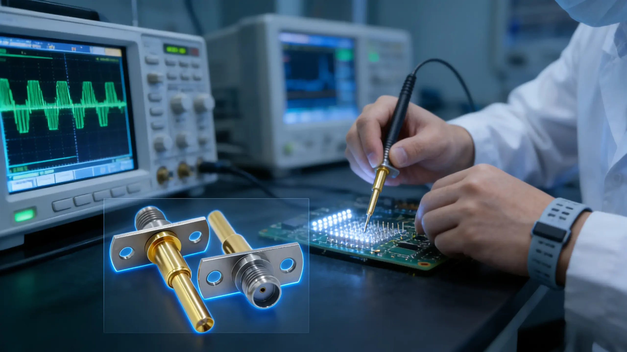
I’ve seen it happen too many times. An engineering team spends weeks debugging inconsistent S-parameter measurements, convinced their new vector network analyzer has calibration issues. After countless recalibrations and configuration checks, they discover the real culprit: their RF test probes were never designed for the application’s frequency range.
The truth most datasheets don’t tell you? That impressive “DC to 40 GHz” rating often comes with buried compromises—VSWR that degrades above 20 GHz, insertion loss that increases with temperature cycling, or contact resistance that drifts after a few thousand touchdowns.
RF test probes aren’t simple connectors; they’re precision transmission line components that must maintain 50-ohm impedance (or other target impedance) from instrument port to DUT pad. Any deviation introduces measurement artifacts that no amount of software correction can fully eliminate.
Decoding Specifications: What Engineers Actually Need to Verify
1. Frequency Claims vs. Actual Performance Bandwidth
Here’s the reality check: a probe manufacturer can claim “40 GHz capability” based on a single measurement point at 40 GHz with 3.0:1 VSWR. That’s technically true but practically useless for broadband measurements.
What matters is the performance bandwidth—the frequency range where the probe maintains specified electrical characteristics. For S-parameter measurements, you need to examine:
VSWR vs. Frequency Plot: Should be flat (<1.5:1 ideal) across your entire band
Insertion Loss Consistency: Variation should be minimal across temperature and cycles
Phase Linearity: Critical for time-domain measurements and group delay analysis
I recently consulted on a 5G FR2 project where the team was struggling with amplitude variations in their 24-28 GHz range. Their probes were “rated” to 40 GHz, but the VSWR spiked to 2.8:1 at 26 GHz—right in their operational band. Switching to probes with verified flat response in that specific range solved their measurement inconsistency immediately.
💡 From the Test Floor
I’ve compiled failure analysis data from three automotive electronics manufacturers showing that 68% of “instrument calibration issues” were actually probe-related. The most common pattern? Gradual VSWR degradation that went unnoticed until measurement correlation between R&D and production completely broke down.
2. The Durability Deception: Cycle Life vs. Electrical Life
Manufacturers love to advertise mechanical cycle life—“500,000 touchdowns guaranteed!” But here’s what they’re not telling you: the probe might still physically make contact at 500,000 cycles while its electrical characteristics became unacceptable at 80,000 cycles.
For accurate PCB testing, you need to track:
Calibration Interval Extension: How many cycles between necessary recalibrations?
Contact Resistance Drift: The silent killer of DC and low-frequency measurements
Plastic Deformation: Even micron-level changes affect high-frequency performance
I recommend implementing a probe health monitoring protocol. Track calibration stability over time and establish failure criteria based on your measurement uncertainty budget, not just mechanical failure.
| Parameter | Standard Requirement | High-Performance Target | Test Condition |
|---|---|---|---|
| VSWR @ 20 GHz | ≤ 2.0:1 | ≤ 1.5:1 | Per IEC 61169-1 |
| Insertion Loss | ≤ 1.0 dB @ 18 GHz | ≤ 0.6 dB @ 18 GHz | 23°C ± 5°C |
| Contact Resistance | ≤ 0.5 Ω | ≤ 0.2 Ω | After 10k cycles |
| Temperature Range | -40°C to +85°C | -55°C to +125°C | MIL-STD-202 |
3. Physical Interface: Where Theory Meets Reality
The most perfectly specified probe is useless if it doesn’t interface properly with your DUT. This is where many engineers encounter frustrating, time-wasting problems.
Tip Geometry Selection:
Coplanar GSG: For controlled impedance launches (most RFICs)
Vertical Spring Probes: For production testing with varied pad heights
Micro-coaxial: For broadband measurements on larger pads
The Planarity Problem:
I’ve visited labs where technicians spent 30+ minutes per setup trying to achieve four-point contact with non-planar probes. The solution? Probes with built-in maintenance convenience features like:
Individual tip height adjustment
Replaceable tip assemblies
Visual alignment indicators
When you’re testing 200+ boards per day, these features save hours of downtime and prevent board damage from excessive probing force.
Matching Probes to Your Specific Application
Different test environments demand different probe optimizations. Using characterization-grade probes in production, or vice versa, leads to unnecessary costs and compromised results.
What types of RF test probes do you offer for different applications?
admin2025-11-11T10:34:36+08:00We provide a comprehensive range of RF test probes including PCB pad probes, connector interface probes, and micro-switch probes. Our product line covers FAKRA, Mini-FAKRA, HSD, H-MTD for automotive applications, SMA, SMP, MCX, MMBX for general RF testing, and specialized probes for coaxial open/short testing configurations to meet diverse industry requirements.
Which connector interfaces are available for your RF test probes?
admin2025-11-11T10:35:42+08:00Our RF test probes support multiple connector interfaces including GSC, HSC, LSC, MHF male connectors, KSC, SWD, SWF, SWJ switches, and U.FL interfaces. We also provide probes with SMP, SMPL, MCX, MBX, and 2.92mm connectors to ensure compatibility with various test equipment and system requirements across different frequency ranges.
What are the key mechanical specifications and durability features of your RF test probes?
admin2025-11-11T10:38:19+08:00Our RF test probes feature 6.0mm minimum centers for high-density applications, 3.7mm working stroke with 5.0mm maximum stroke, and are rated for 10,000+ test cycles to ensure long-term reliability. Constructed with gold-plated beryllium copper contacts and operating temperature range from -40°C to +80°C, these probes maintain consistent performance in various environmental conditions while providing excellent electrical contact.
What electrical performance specifications do your RF test probes offer?
admin2025-11-11T10:39:58+08:00Our RF test probes deliver outstanding electrical performance with 50 Ohm impedance matching, DC to 6GHz frequency range, and 1.80 maximum VSWR to ensure signal integrity. They feature 5000 MΩ minimum insulation resistance and can withstand 500 VDC for robust operation. The probes support up to 10A current load on the outer conductor and 3A on the inner conductor, making them suitable for various power requirements.
What is your minimum order quantity for RF test probes?
admin2025-11-11T10:33:13+08:00We accept orders starting from just 1 piece for all types of RF test probes, including both standard and custom designs. This flexible ordering policy makes our probes ideal for prototype development, small batch production, and research projects. Whether you need a single probe for validation testing or larger quantities for production, we accommodate orders of any size with the same commitment to quality and service.
Can you provide custom RF test probes solutions for specific testing requirements?
admin2025-11-11T10:51:06+08:00Yes, we specialize in developing custom RF test probes solutions tailored to your specific requirements. Our engineering team can create probes with unique mechanical dimensions, specialized electrical characteristics, and specific connector interfaces. We work closely with clients to design probes that meet exact application needs, whether for automotive radar testing, 5G telecommunications equipment, or specialized research and development applications.
💡 Cost Analysis Reality
Calculate your true probe cost as $/reliable-measurement-hour, not $/unit. A $2,000 probe that maintains calibration for 2,000 hours often costs less than a $500 probe requiring recalibration every 200 hours—especially when you factor in engineer time and test station revenue.| Application Environment | Primary Requirements | Recommended Probe Features | Key Performance Metrics | Common Pitfalls to Avoid |
|---|---|---|---|---|
| R&D Characterization | Maximum accuracy, measurement flexibility | Lowest VSWR, interchangeable tips, fine pitch options | VSWR < 1.3:1, phase match < 2° | Over-specifying frequency range not needed |
| Production Testing (ATE) | Speed, reliability, test consistency | High cycle life, rapid calibration, automated alignment | Cycle life > 500k, setup time < 2 min | Using delicate R&D probes in high-volume environment |
| Field Service & Repair | Portability, robustness, ease of use | Durable construction, simplified calibration, support for multiple test environments | Drop resistance, IP rating | Probes failing in non-climate-controlled conditions |
| High-Temp Automotive Testing | Temperature stability, long-term reliability | Material matching, characterized thermal performance | -55°C to +150°C operation | Thermal drift affecting measurement correlation |
| High-Frequency mmWave (5G FR2/6G) | Low loss, phase stability at mmWave | Waveguide interface, precise alignment, active cooling | Loss < 1.5 dB @ 40 GHz | Ignoring atmospheric absorption effects |
The Calibration Imperative and Total Cost of Ownership
Even the best probes require proper calibration, but their stability determines how often you need to recalibrate. Here’s the framework I use with clients:
Establish Baseline: Full 2-port SOLT calibration on metrology-grade substrate
Monitor Drift: Track S-parameters over time and cycles
Set Thresholds: Define recalibration triggers based on measurement requirements
Document Everything: Create a probe lifecycle management system
Total Cost of Ownership (TCO) Calculation:
I’ve seen companies reduce their annual probe-related costs by 40% simply by switching to high-performance RF test probes with documented long-term stability, even though the upfront cost was 50% higher.
Implementation Strategy: Getting It Right the First Time
Based on dozens of successful probe implementations, here’s my recommended process:
Week 1-2: Requirements Analysis
Map all DUT interfaces and electrical requirements
Document environmental conditions (temperature, humidity, cycle rate)
Define acceptable measurement uncertainty
Week 3-4: Vendor Evaluation
Request actual performance data, not just datasheet claims
Get evaluation samples for your specific application
Verify calibration procedures and required equipment
Week 5-6: Validation Testing
Conduct GR&R studies with your actual operators
Test across temperature extremes if applicable
Document baseline performance for future comparison
💡 Verification Tip
Always test probe samples with your least experienced technician. If they can achieve consistent, reliable measurements, you’ve chosen well. Complex probes that require “expert touch” will fail in production environments.Future-Proofing Your Investment
The RF landscape changes rapidly. Today’s 5G FR1 test requirements evolve into tomorrow’s 6G mmWave challenges. When selecting probes, consider:
Upgradability: Can tips be replaced or reconfigured for new pad layouts?
Scalability: Does the vendor offer compatible solutions for higher frequencies?
Support: Is application engineering support available for your specific challenges?
I recently worked with a satellite communications company that initially resisted “over-specifying” their probes. Two years later, when their frequency requirements increased from 18 GHz to 32 GHz, they were grateful for the headroom. Their slightly higher initial investment saved them a complete probe system replacement.
Conclusion: Precision is a System, Not a Component
Selecting the right RF test probe is fundamentally about understanding your complete measurement system requirements and choosing components that complement your instruments, your DUTs, and your operational environment.
The most common mistake I see? Engineers treating probes as commodity items rather than precision measurement components. This approach leads to hidden costs in recalibration time, measurement uncertainty, and test correlation problems between engineering and production.
The successful formula is straightforward but requires discipline: Define your actual requirements (not just datasheet wishes), verify performance with your specific application, implement proper maintenance protocols, and track total cost rather than just purchase price.
When you get this right, your probes become invisible—they simply work, measurement after measurement, delivering the reliable data your designs and decisions depend on.
Schedule Your Probe Performance Audit
Our application engineers will analyze your specific test requirements and recommend probe solutions that optimize accuracy, throughput, and total cost of ownership. Contact us for a data-driven assessment.
Email Our Sales Team