
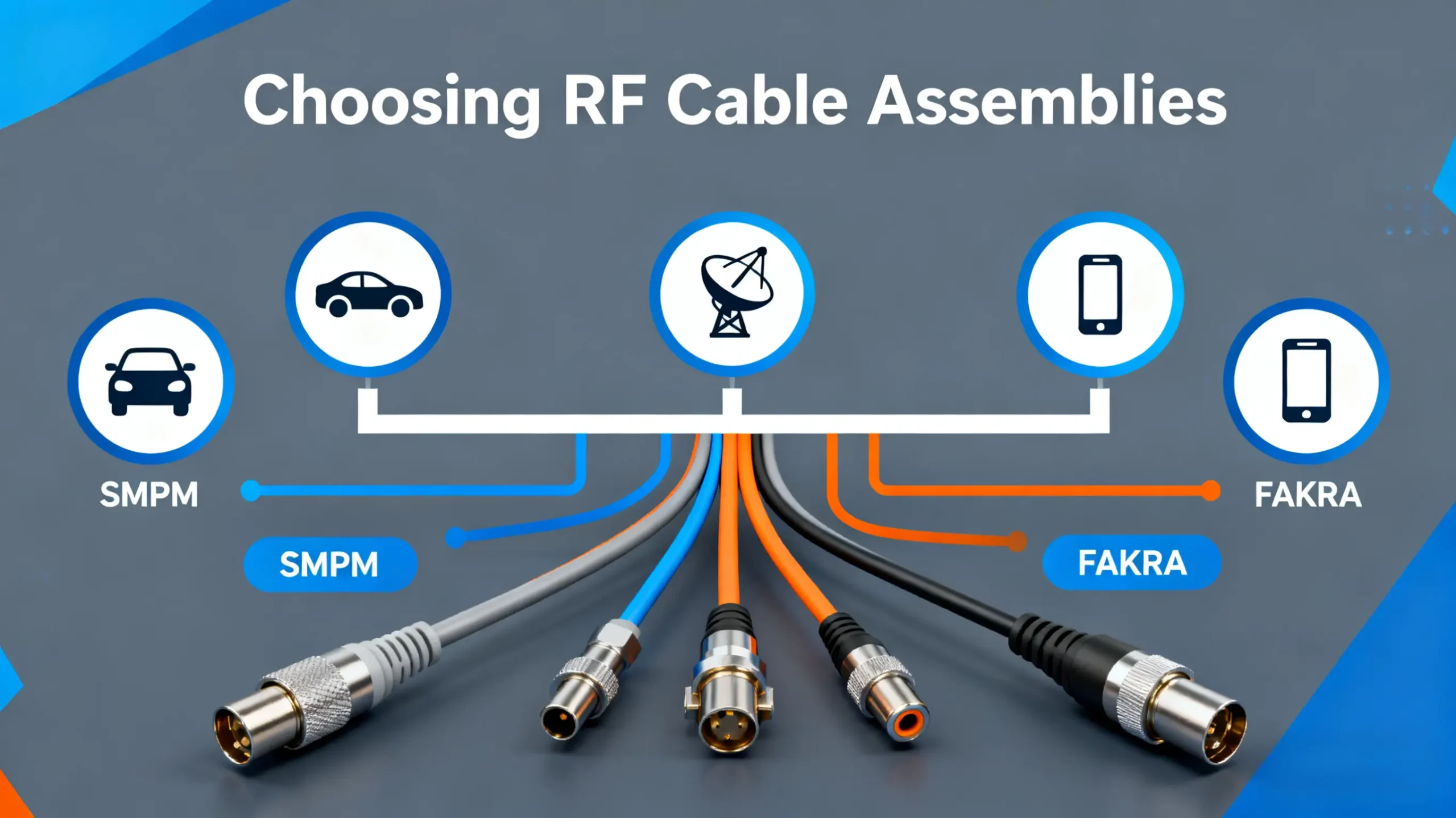
📝 Key Points Summary
The Hidden Costs of RF Cable Compromises
Picture this: after weeks of debugging, you discover that inconsistent test results stem from a simple RF cable that seemed perfectly adequate. This scenario plays out daily in labs and production floors worldwide. The right RF cable assembly isn’t just another component—it’s the foundation of reliable signal transmission. Whether you’re validating 5G modules, testing automotive radar, or characterizing satellite communications, your measurements are only as good as your cabling.
Many engineers discover too late that a poorly chosen cable can mask real performance issues or create artificial problems. The consequences extend beyond failed tests to include production delays, costly rework, and compromised product quality. Understanding how to select the proper RF cable assembly is therefore not just technical knowledge—it’s business-critical expertise.
A Practical Framework for RF Cable Selection
Electrical Performance: The Non-Negotiable Foundation
Frequency Range and VSWR: The Critical Partnership
Your operating frequency dictates everything about cable selection. A cable rated for 3 GHz will severely degrade signals at 6 GHz, while one rated for 40 GHz would be overkill—and unnecessarily expensive—for sub-6 GHz applications. The Voltage Standing Wave Ratio (VSWR) specification tells you how much signal reflects back due to impedance mismatches. For precision measurements, target VSWR below 1.5:1 across your frequency band.
The Insertion Loss Reality
All cables attenuate signals—this is insertion loss in action. The longer the cable and higher the frequency, the greater the loss. While datasheets provide nominal values, real-world performance varies with bending, temperature, and connector wear. A 3 dB loss means half your signal power disappears before reaching the device under test. For critical applications, consider low-loss alternatives despite their higher cost.
Connector Selection: Matching Interface to Application
The connector forms the critical junction between your cable and equipment. Different connector types balance frequency performance, physical size, durability, and cost.
| Connector Type | Frequency Range | Mating Mechanism | Primary Applications |
|---|---|---|---|
| SMPM | DC to 6 GHz | Push-on | High-density test systems, compact designs |
| FAKRA | DC to 6 GHz | Keyed lock | Automotive systems, infotainment |
| 2.92mm | DC to 40 GHz | Threaded | Millimeter-wave R&D, precision measurements |
| N-Type | DC to 11 GHz | Threaded | Base station, infrastructure, rugged environments |
SMPM: Space-Constrained Excellence
The SMPM (Super Miniature Push-on Micro) connector excels where real estate is precious. Its compact push-on design makes it ideal for automated test equipment and high-density applications. However, the convenience of quick mating comes with an important caveat: always verify positive engagement to avoid intermittent connections during vibration or movement.
FAKRA Connectors: Automotive Reliability Standard
The FAKRA connector system brings essential standardization to automotive RF applications. With color-coded housings and mechanical keying, these connectors prevent mismating in complex vehicle systems. If you work with automotive radar, telematics, or infotainment systems, understanding the FAKRA ecosystem is not optional—it’s essential for reliability and compliance.
💡 Production Reality
In automotive end-of-line testing, we’ve documented that cable failures account for over 30% of test station downtime. The right cable specification doesn’t just improve measurements—it significantly impacts manufacturing throughput and product quality.
Application-Specific Selection Guidelines
Different applications demand different cable characteristics. What works perfectly in a laboratory environment may fail miserably on a production floor or outdoor installation.
| Application Scenario | Recommended Series | Critical Performance Factor |
|---|---|---|
| Automotive Radar Testing | FAKRA, H-MTD | Phase stability, temperature cycling |
| 5G Base Station Installation | 4.3-10, N-Type | Weather sealing, power handling |
| Laboratory Metrology | 2.92mm, 3.5mm | Measurement repeatability, precision |
| High-Volume Production Test | SMPM, Mini-FAKRA | Durability, mating cycle life |
Automotive Electronics: Beyond Basic Connectivity
Automotive radar testing presents unique challenges that go far beyond selecting the proper FAKRA connector variant. Engineers must consider how temperature cycling from -40°C to +105°C affects phase performance and how constant vibration impacts connection integrity. The cable must maintain stable electrical characteristics while withstanding the rough handling typical in production environments.
Telecommunications Infrastructure Demands
Base station installations demand completely different priorities than laboratory settings. Here, environmental sealing becomes as important as electrical performance. Look for connectors with IP67 ratings when cables will be exposed to weather elements. For rooftop and tower installations, consider how UV radiation and extreme temperature swings will affect cable performance over years of service.
💡 Technical Insight
The actual phase stability of cable assemblies can vary by ±5° between manufacturers claiming identical specifications. For phase-sensitive applications like radar testing, always request validation data rather than relying on datasheet values alone.
High-Volume Production Testing Economics
In manufacturing test environments, durability often trumps ultimate precision. A cable that survives 10,000 mating cycles with slightly higher insertion loss may be far preferable to a precision cable that fails after 2,000 cycles. The economics of production downtime frequently justify investing in more robust—though potentially less precise—cable solutions.
Supplier Evaluation: Asking the Right Questions
Technical specifications tell only part of the story. When selecting a cable supplier, these often-overlooked factors can make the difference between a successful project and ongoing frustrations.
Engineering Support Accessibility
Can you discuss your application directly with an engineer who understands both RF theory and practical implementation challenges? The best suppliers provide technical support that helps optimize your selection rather than just processing orders.
Customization Capabilities
Standard products rarely perfectly match unique requirements. Look for suppliers offering custom RF cable assemblies with reasonable lead times. The ability to specify exact lengths, connector combinations, and performance parameters indicates true engineering capability rather than just distribution.
Quality Assurance Transparency
Always request sample test data for similar assemblies. Reputable suppliers document performance validation and can provide detailed reports showing actual VSWR, insertion loss, and phase measurements. Ask about their calibration standards and measurement uncertainty—evasive answers should raise red flags.
What is the minimum order quantity for RF Cable Assemblies?
admin2025-11-11T10:09:47+08:00We accept orders starting from just 1 piece, whether for standard or custom RF Cable Assemblies. There is no minimum order quantity required, making it ideal for prototype development, small batch production, and research projects. Custom RF Cable Assemblies are also available with the same flexible ordering policy.
What are the main types of rf cable assemblies and their applications?
admin2025-11-11T10:14:10+08:00RF Cable Assemblies include semi-rigid, flexible, and phase-stable types. Semi-rigid assemblies offer superior electrical performance for test and measurement applications. Flexible RF Cable Assemblies provide better maneuverability for field service and installation. Phase-stable RF Cable Assemblies maintain consistent electrical characteristics for precision applications like automotive radar and aerospace systems.
How do I select the right rf cable assemblies for frequency requirements?
admin2025-11-11T10:16:38+08:00Choose rf cable assemblies based on your operating frequency range. For applications up to 6 GHz, SMPM and FAKRA rf cable assemblies are suitable. For 6-40 GHz requirements, consider 2.92mm rf cable assemblies. Millimeter-wave applications above 40 GHz require specialized rf cable assemblies with precision connectors like 1.85mm.
What industries commonly use rf cable assemblies?
admin2025-11-11T10:18:12+08:00Rf cable assemblies serve multiple industries including telecommunications (5G infrastructure, base stations), automotive (radar systems, ADAS testing), aerospace and defense (avionics, radar), medical equipment (imaging systems), and research institutions (laboratory measurements, R&D validation).
What are the key specifications to evaluate in rf cable assemblies?
admin2025-11-11T10:19:51+08:00Critical specifications for rf cable assemblies include VSWR (typically 1.3:1 or better), insertion loss, impedance (50-ohm standard), frequency range, power handling capacity, phase stability, and operating temperature range. High-quality rf cable assemblies maintain consistent performance across all specifications.
Can rf cable assemblies be customized for specific requirements?
admin2025-11-11T10:21:19+08:00Yes, rf cable assemblies can be customized with various connector types, cable lengths, impedance matching, and specialized coatings. Custom rf cable assemblies are available for extreme environments, high-vibration applications, and specific mechanical constraints.
💡 Procurement Strategy
When requesting quotes for custom assemblies, provide complete application details rather than just technical specifications. This enables suppliers to recommend optimizations that may improve performance or reduce total cost of ownership.
Making Confident RF Cable Decisions
Selecting the right RF cable assembly requires balancing multiple factors: electrical requirements, mechanical constraints, environmental conditions, and application-specific demands. By applying the systematic approach outlined here—carefully evaluating your frequency needs, connector interface requirements, durability expectations, and operating environment—you can make informed decisions that ensure measurement integrity and system reliability.
Remember that the most expensive cable isn’t necessarily the best for your application, but the cheapest option often carries hidden costs through compromised measurements, frequent replacement, and system downtime. Invest time in proper selection, and your cables will become transparent contributors to measurement success rather than sources of uncertainty and frustration.
Optimize Your RF Testing Infrastructure
Get expert assistance selecting the ideal RF cable solutions for your specific application. Our engineering team provides personalized recommendations backed by comprehensive technical support and performance validation.
Email Our Sales Team