Selecting the perfect RF test probe is more than a mere procurement step; it’s a critical engineering decision that can make or break the accuracy of your high-frequency measurements. Whether you’re validating a new 5G prototype or ensuring quality in mass production, the right probe is your gateway to reliable data. This comprehensive guide is designed to help procurement engineers and RF professionals navigate the key technical considerations, avoid common pitfalls, and make an informed choice that balances performance, durability, and cost.
💡 Key Points
- Precision is Paramoun: The wrong RF probe introduces measurement errors that can compromise your entire design or production line, making technical specifications your top priority.
- No One-Size-Fits-All: Your application—be it R&D lab work or high-volume manufacturing—directly dictates the ideal probe type, balancing bandwidth, durability, and cost.
- Proactive Maintenance Pays Off: Even the best probe will fail without proper care. Regular inspection, cleaning, and performance verification are non-negotiable for long-term accuracy and ROI.
What Is an RF Test Probe and How Does It Work?
At its core, an RF test probe is a precision interface used to connect a measurement instrument, like a vector network analyzer (VNA) or spectrum analyzer, to a device under test (DUT). Its primary role in RF signal testing is to transmit high-frequency signals from the source to the test point and back with minimal degradation, enabling accurate characterization of components like amplifiers, filters, and PCBs.
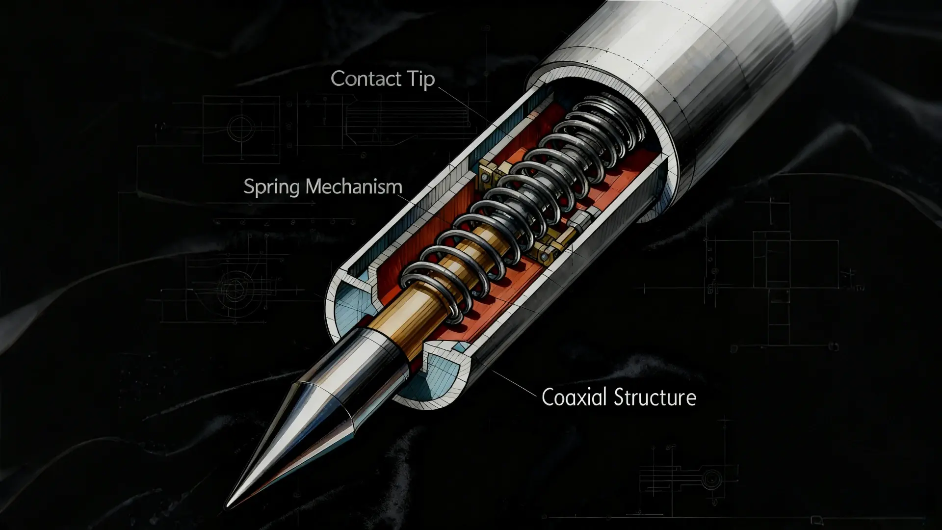
So, how does it work? An RF probe typically features a central conductor (the contact tip) that makes a physical and electrical connection to a specific test point on a circuit board—such as a pad, via, or connector. This tip is surrounded by a grounded outer shield to prevent signal radiation and interference. The probe is connected to the test equipment via a coaxial cable assembly.
The magic lies in its internal design, which is engineered for critical functions like impedance matching to prevent signal reflections that distort measurements. Key to its operation is ensuring low signal loss and maintaining signal integrity by providing a stable, repeatable contact. This makes RF probes indispensable tools for precise PCB testing and validation across the development lifecycle.
Key Factors to Consider When Choosing an RF Test Probe
Choosing an RF probe isn’t a one-size-fits-all process. It requires a careful evaluation of several technical parameters to match your specific application.
Frequency Range and Bandwidth
This is the most fundamental specification. The probe’s operational frequency must cover, and ideally exceed, the fundamental frequency and harmonics of your DUT. Using a probe with insufficient bandwidth will attenuate higher-frequency components, leading to inaccurate measurements of both the fundamental signal and its critical harmonics.
Impedance Matching (Typically 50 ohms)
The standard characteristic impedance for most RF systems is 50 ohms. It is crucial that the probe matches this impedance along the entire signal path to minimize reflections, which are quantified by the Voltage Standing Wave Ratio (VSWR). A significant impedance mismatch will degrade signal integrity and render your S-parameter measurements unreliable.
Contact Stability and Spring Durability
A probe is only as good as its contact. The internal spring mechanism must provide consistent, reliable pressure with every touch-down. A worn-out or weak spring leads to intermittent connections and unstable readings, especially in high-volume production testing. Look for probes rated for high cycle life (e.g., 200,000+ touch-downs) for demanding environments.
Insertion Loss and VSWR Performance
Insertion loss is the measure of signal power lost through the probe itself. Lower is always better, as it means more of your signal is reaching the instrument. VSWR measures the efficiency of power transfer; a VSWR of 1:1 is perfect, and a lower value (e.g., 1.5:1 within the band) indicates fewer reflections and better performance. Always review these specs across your entire frequency band.
Connector Compatibility and Cable Type
Ensure the probe’s interface (e.g., 2.92mm, 3.5mm, or 1.85mm) matches your test equipment and coaxial cables. The quality, flexibility, and phase stability of the attached cable also directly impact overall system loss and ease of use.
What technical support do you provide for test modules integration?
admin2025-11-11T13:44:04+08:00We offer complete technical support throughout the integration process. Our engineering team provides detailed application guidance, performance optimization advice, and troubleshooting assistance to ensure successful implementation of your test modules in various testing environments.
What quality assurance measures do you implement for test modules?
admin2025-11-11T13:43:10+08:00Every test module undergoes comprehensive quality validation, including impedance matching verification, signal integrity analysis, and mechanical cycle life testing. This rigorous process ensures all delivered test modules meet our strict performance and reliability standards.
Can you customize test modules for specific testing requirements?
admin2025-11-11T13:42:02+08:00We specialize in developing custom test modules tailored to unique application needs. Our engineering team can modify probe configurations, interface types, and performance specifications to create bespoke solutions that address your specific device validation challenges.
What is the typical lead time for standard test modules?
admin2025-11-11T13:40:40+08:00For standard test modules configurations, our typical production lead time ranges from 2 to 3 weeks. This efficient turnaround applies even to single-unit orders, ensuring you receive your required test modules promptly to maintain your project development schedule.
What are the main application areas for your test modules?
admin2025-11-11T13:38:59+08:00Our comprehensive range of test modules serves diverse testing applications across multiple industries. These include semiconductor wafer validation, high-frequency RF component testing, and PCB in-circuit functional verification, providing reliable solutions from R&D labs to production floors.
💡 Pro Tip
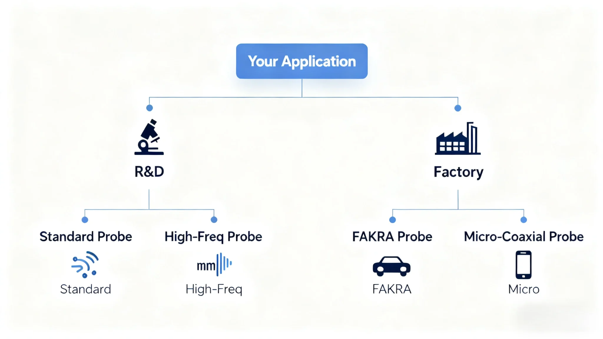
- For R&D and Lab Testing: Prioritize performance. Choose probes with the widest bandwidth, lowest VSWR, and lowest insertion loss for maximum accuracy, even if they are more delicate or expensive.
- For Mass Production: Prioritize durability and speed. Select probes designed for high cycle life, with robust spring pins and quick-connect interfaces to maximize throughput and uptime.
Types of RF Test Probes and Their Applications
Different testing scenarios call for specialized probes. Understanding the categories is key to selecting the right tool.
Standard RF Test Probes
These are the workhorses for general PCB testing and component validation. They are designed for common interfaces and frequency ranges up to several GHz, suitable for checking connectors and basic circuit functionality. They offer a great balance of performance and cost for everyday tasks.
High-Frequency and Millimeter-Wave Test Probes
As technologies like 5G and millimeter-wave (e.g., 28GHz, 39GHz, and beyond) advance, probes capable of operating at these frequencies are essential. These probes are precision-engineered with advanced materials for minimal dielectric loss and superior shielding to enable accurate high-frequency measurement of RFICs, advanced communication modules, and radar systems.
Application-Specific Probes (FAKRA / IPEX)
Specifically designed for the automotive and compact wireless device industries. FAKRA probes are key for automotive RF testing, connecting to standardized vehicle antenna, GPS, and camera modules. IPEX/MHF probes are used for testing the tiny coaxial connectors found inside smartphones, tablets, and IoT modules.
Customized RF Test Probes
When standard solutions don’t fit, custom probes are the answer. They can be tailored for non-standard pitch sizes, unique landing pad geometries, or specialized frequency bands, providing flexibility for proprietary designs and cutting-edge applications. This is often a necessary route for innovative products without industry-standard test interfaces.
Common Mistakes When Selecting RF Test Probes (And How to Avoid Them)
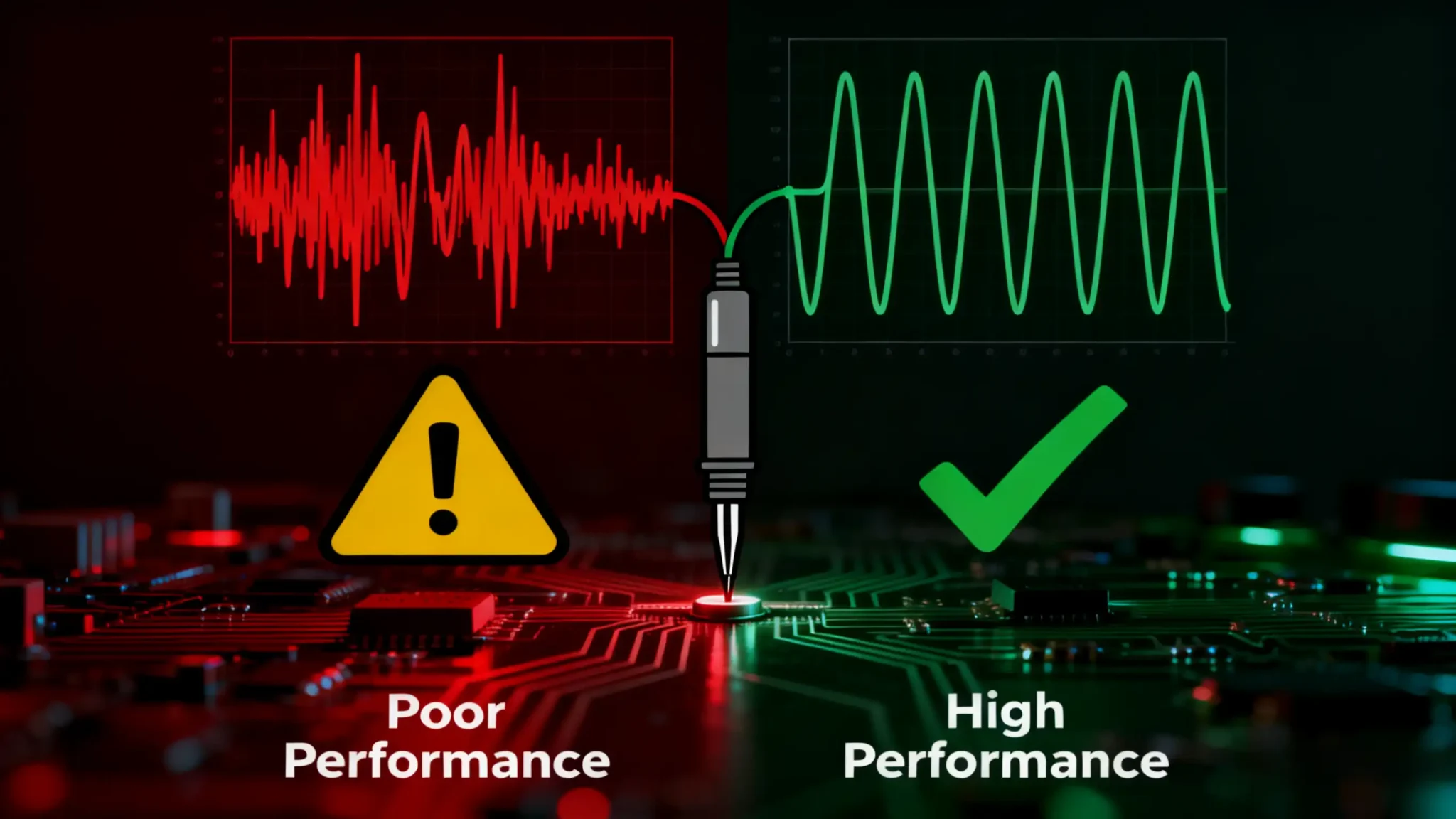
Avoiding these common errors can save time, money, and prevent flawed data.
Mistake #1: Underestimating the Required Frequency Range
Don’t: Select a probe based solely on the fundamental frequency of your signal.
Do: Choose a probe with a bandwidth that covers at least the 3rd or 5th harmonic of your signal. This is crucial for accurate time-domain (TDR) analysis and understanding signal integrity for digital or modulated waveforms.
Mistake #2: Ignoring Impedance Mismatch and VSWR
Don’t: Assume all “50-ohm” components are created equal. A chain is only as strong as its weakest link.
Do: Carefully review the VSWR specification across your entire frequency band of interest. Ensure all components in the chain (cable, adapter, probe) are well-matched to prevent cumulative reflections that distort measurements.
Mistake #3: Compromising on Contact Quality for Cost
Don’t: Opt for cheap, unproven probes for a critical production line. Inconsistent contact leads to test escapes and product returns.
Do: Invest in probes with high-quality, gold-plated contact tips and durable, precisely calibrated spring mechanisms. This guarantees stable electrical contact and long-term mechanical reliability, protecting your bottom line.
💡 Pro Tip
Factor in the total cost of ownership. A slightly more expensive, durable probe that lasts for 500,000 cycles is far more economical than a cheap one that fails after 50,000 and causes production downtime.
How to Test and Maintain Your RF Test Probe
Proper care is essential for preserving the performance and lifespan of your investment.
Inspect Before Use: Regularly check the spring force and examine the contact tip under a microscope for signs of wear, contamination, or damage. A damaged tip can ruin expensive device under test (DUT) pads.
Keep It Clean: Keep probe surfaces clean from dirt, skin oils, and oxidation. Use isopropyl alcohol and lint-free swabs for cleaning. Proper storage in protective, labeled cases is mandatory.
Apply Proper Pressure: Use the manufacturer’s recommended contact pressure and avoid excessive overdrive, which can damage both the probe’s internal mechanism and the device under test.
Verify Performance: Periodically verify signal accuracy through calibration and performance checks against a known standard or using a calibration substrate. This is the only way to confidently trust your measurement data.
| Specification | Why It Matters | Good Value (e.g., for a 20GHz Probe) | Poor Value |
|---|---|---|---|
| Frequency Range | Determines the highest signal frequency that can be accurately measured. | DC to 20 GHz | DC to 6 GHz |
| VSWR | Measures impedance matching; lower values mean fewer reflections and better accuracy. | < 1.5:1 up to 20 GHz | > 2.0:1 at high frequencies |
| Insertion Loss | Amount of signal power lost through the probe; impacts dynamic range. | < 1.0 dB at 20 GHz | > 2.0 dB at 20 GHz |
| DC Resistance | Resistance of the signal path; affects power delivery and bias. | ~0.5 ohms | > 2.0 ohms |
| Cycle Life | The number of reliable touch-downs before performance degrades. | > 200,000 cycles | < 50,000 cycles |
Why Choose REECUFUTURE for Your RF Test Probes
In a field where precision is paramount, partnering with a trusted manufacturer is crucial. At REECUFUTURE, we stand as a professional RF testing component manufacturer dedicated to empowering engineers with reliable and high-performance measurement solutions.
We specialize in the precision manufacturing of a wide range of products, including RF Test Probes, RF Connectors, and High-Frequency Probes. Our core strengths lie in delivering products that excel in the areas that matter most: exceptionally low signal loss, superior stable contact achieved through rigorous spring force control, and the flexibility to provide flexible customization for your unique application challenges. Explore our full range of solutions on our RF Test Probes.
We understand that innovation starts with a single unit. That’s why we offer a minimum order quantity: 1 piece, making REECUFUTURE the ideal partner for both initial prototyping and high-volume mass production. Our commitment to quality ensures that every probe we ship is built to the highest standards, helping you secure accurate data and accelerate your time-to-market.
💡 Pro Tip
Your Measurement, Our Mission: Don’t let an inferior probe be the weakest link in your test chain. From concept to volume production, we provide the precision tools you need to be confident in your results.