
🔌 Key Points
Navigating the Miniature RF Landscape
In the tightly packed world of modern electronics—from WiFi modules and 5G devices to compact IoT sensors—board space is a premium. This drive for miniaturization led to the widespread adoption of IPEX (sometimes called U.FL) antenna connectors, a family of ultra-small, coaxial RF interfaces. However, a common and costly pitfall arises from a simple oversight: treating all IPEX connectors as the same.
Engineers often discover too late that an IPEX I and an IPEX II connector are not mechanically interchangeable. Plugging a mismatched cable or, critically, using the wrong test probe can lead to poor connection, damaged sockets, and degraded RF performance that sabotages wireless range and reliability. This guide cuts through the confusion. We’ll clearly differentiate between IPEX generations and, more importantly, demonstrate how to accurately test them using the right RF pogo pins, ensuring your design performs as intended from prototype to volume production.
Mechanical & Electrical Showdown: IPEX I vs. IPEX II
Understanding the physical and electrical differences is the first step to avoiding integration headaches.
Dimensional Differences: Why Force-Fitting Fails
The most critical distinction is mechanical. The IPEX II (MHF® II) connector introduced a slightly larger and more robust locking mechanism compared to the original IPEX I (MHF® I). Attempting to mate an IPEX I plug with an IPEX II socket, or vice versa, will not work and risks permanently deforming the fragile spring-loaded center pin in the socket. This is the primary source of field failures attributed to “bad connectors”—often, they were simply the wrong generation.
Performance at Millimeter Wave Frequencies
While both are designed for high-frequency applications, their performance subtly diverges as frequencies climb into the millimeter-wave range (above 6 GHz). The IPEX II’s revised design typically offers marginally better impedance control and lower insertion loss at these extreme frequencies, a factor crucial for cutting-edge applications like WiGig (60 GHz) or automotive radar. For most WiFi and cellular bands, however, both provide excellent performance when correctly mated.
💡 The Real Cost of a Mismatch
It’s not just a one-time assembly error. In a production test scenario, using a pogo pin designed for IPEX I on an IPEX II board (or the opposite) creates an inconsistent and poor-quality electrical contact. This variable contact resistance directly translates into unreliable S-parameter measurements (like Return Loss), causing good boards to fail test and faulty boards to pass. The financial drain from yield loss and escaped defects far outweighs the cost of using the correct probe.
The Critical Role of RF Pogo Pins in Testing
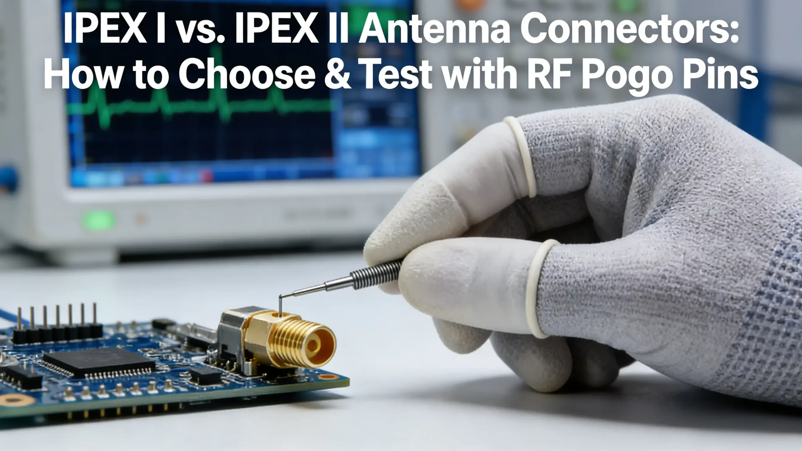
You cannot reliably test an RF connector with a DC probe. A proper RF pogo pin is a precision coaxial transmission line in a spring-loaded package, engineered to become a transparent part of your measurement system.
What Makes an RF Pogo Pin Different?
A generic pogo pin is designed for low-frequency continuity checks. An RF pogo pin is engineered for radio frequencies. Its core construction features a controlled 50-ohm impedance from tip to tail, using a precise coaxial geometry with a center conductor, dielectric insulator, and outer shield. This minimizes signal reflection (VSWR) and loss, ensuring the measured data reflects the Device Under Test (DUT), not the test fixture. Furthermore, its spring force and tip geometry are tailored to engage the specific depth and center pin of the IPEX socket without applying damaging lateral force.
Consequences of Using a Standard Probe
Using a standard probe introduces a significant discontinuity in the RF path. It acts as a tiny antenna, radiating energy and causing unpredictable impedance mismatches. Your Vector Network Analyzer (VNA) will measure this compounded effect, making it impossible to discern whether a poor Return Loss reading is from the connector under test or the probe itself. This renders your validation data meaningless and design decisions guesswork.
| Parameter | Typical IPEX I (MHF® I) Spec | Typical IPEX II (MHF® II) Spec | Impact on Test Probe Selection |
|---|---|---|---|
| Mating Height | Approx. 1.20 mm | Approx. 1.45 mm | Probe travel/scrub must match to achieve proper contact without bottoming out. |
| Center Contact Diameter | ~0.30 mm | ~0.38 mm | Probe tip crown geometry must be sized to make reliable contact without slipping. |
| Frequency Range | DC to 6+ GHz | DC to 8+ GHz (optimized) | The selected RF pogo pin must have a VSWR spec that is flat across your DUT’s operating band. |
| Impedance | 50 Ω | 50 Ω | The probe must maintain a stable 50 Ω impedance to prevent measurement errors. |
| Durability (Mating Cycles) | ~30 cycles | ~60 cycles | Test probes for production must far exceed this (10k+ cycles) to remain stable over time. |
Building a Reliable Test Strategy
Selecting the right probe is half the battle; implementing a correct test methodology is the other.
Step 1: Positive Generation Identification
Before designing a test fixture, visually and mechanically verify which IPEX generation is on your board. Use a datasheet or a known-good sample connector for comparison under a microscope if necessary. Never assume.
Step 2: Fixture Design for Precision and Repeatability
The pogo pin must be held in perfect coaxial alignment with the connector under test. A sloppy or angled approach will damage the socket. Design your test fixture with precise guide holes or mating features that ensure the probe engages straight-on, every time. Incorporate high-frequency cables (like semi-rigid coax) between the probe and your test instrument to preserve signal integrity.
Step 3: Calibration is Non-Negotiable
Always perform a full 2-port VNA calibration (e.g., SOLT) at the plane of the pogo pin tips using appropriate calibration standards. This mathematically removes the systematic errors of your test fixture, cables, and probes from the final measurement. Skipping this step means you are measuring your fixture, not your product.
💡 From R&D Bench to Production Line
In R&D, a manual RF pogo pin with a grippy handle is ideal for one-off validation. On the production line, you need an automated version designed for integration into a test handler—offering the same electrical performance but in a form factor for high-speed, high-cycle life. The testing principle remains identical; only the delivery mechanism changes.
| Application Phase | Primary Testing Goal | How Specialized RF Pogo Pins Enable Success |
|---|---|---|
| Prototype Design Validation | Verify antenna performance & RF path integrity of a new board design. | Provide accurate, repeatable S-parameter measurements to confirm simulations, isolating design flaws from test artifacts. |
| Manufacturing (End-of-Line Test) | Ensure every unit meets RF specifications before shipment at high throughput. | Enable fast, reliable, and non-destructive testing with high durability (50k+ cycles), maximizing yield and minimizing cost of test. |
| Failure Analysis & Rework | Diagnose whether a wireless performance failure is due to the connector, cable, or RF IC. | Allow engineers to selectively probe the IPEX interface with confidence, knowing the measurement is accurate and not causing additional damage. |
| Quality Auditing | Periodically sample units from production to monitor for process drift. | Deliver consistent benchmark data over time, making it possible to identify trends before they become field issues. |
Conclusion: Precision in Every Connection
The journey from a compact PCB to a reliably connected wireless device hinges on mastering the smallest of details. Distinguishing between IPEX I and IPEX II connectors is a fundamental step, but true validation is achieved only when paired with a purpose-built test methodology centered on high-performance RF pogo pins.
Investing in the correct probe is an investment in data integrity. It transforms your test process from a source of variability into a pillar of quality, ensuring that the sophisticated RF performance engineered into your product is fully realized. In an industry where wireless reliability is paramount, the right connection—for both your product and your test equipment—is everything.
Ready to Test Your IPEX Connectors with Confidence?
Stop guessing and start measuring accurately. Explore our range of specialized RF pogo pins engineered for IPEX I, IPEX II, and other micro-connectors. Download detailed specifications or contact our engineering team for support in selecting or customizing the perfect probe for your application.
Email Our Sales Team