
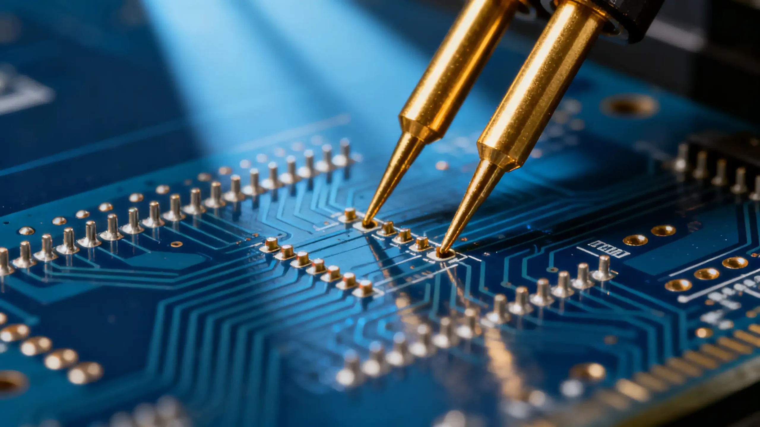
💡 Key Insights for Engineering Excellence
The Evolution of SMT Testing Challenges
The landscape of SMT testing has undergone radical transformation in recent years. Where 0.8mm pitch BGA packages once represented the cutting edge, today’s engineers routinely grapple with 0.3mm pitch μBGA devices. This progression isn’t merely numerical—it represents a fundamental shift in testing paradigms that demands reevaluation of traditional probe selection methodologies.
Redefining Physical Limits: The 0.25mm threshold represents more than just a dimensional barrier; it introduces complex interactions between material science, contact physics, and signal integrity that conventional probe designs cannot adequately address.
🎯 Environmental Note
Current mainstream package pitch has migrated from 0.5mm to 0.3mm, facing the 0.2mm technical threshold next year
Beyond Specifications: The Unwritten Probe Performance Metrics
The Dynamics of Contact Resistance
While datasheets prominently feature initial contact resistance values, the true measure of probe performance lies in its dynamic characteristics. Premium probes maintain impedance variations within 15% of initial values through 100,000 test cycles, whereas standard alternatives may degrade by 40% or more, leading to inconsistent test results and production variability.
Case Analysis: An automotive electronics manufacturer discovered that despite identical initial specifications, Probe Series A maintained stable impedance through thermal cycling while Probe Series B exhibited random fluctuations, resulting in a 7.3% difference in final test yield.
Spring Force Characterization: Beyond Basic Specifications
Spring force represents a dynamic performance curve rather than a static value. Progressive spring mechanisms deliver lower initial contact force to prevent probe skating, then rapidly increase pressure to ensure reliable electrical connection—a critical feature for fine-pitch applications below 0.4mm.
Material Science: The Hidden Performance Driver
Plating Technology Advancements
The relationship between gold plating thickness and probe longevity demonstrates clear engineering trade-offs. Increasing thickness from 0.4μm to 0.8μm can extend operational lifespan by 2.3 times, but at a 60% cost premium. Advanced gradient plating techniques offer an optimal compromise, applying thicker gold in critical contact areas while using cost-effective nickel barriers in non-critical regions.
What industries commonly use rf cable assemblies?
admin2025-11-11T10:18:12+08:00Rf cable assemblies serve multiple industries including telecommunications (5G infrastructure, base stations), automotive (radar systems, ADAS testing), aerospace and defense (avionics, radar), medical equipment (imaging systems), and research institutions (laboratory measurements, R&D validation).
What are the key specifications to evaluate in rf cable assemblies?
admin2025-11-11T10:19:51+08:00Critical specifications for rf cable assemblies include VSWR (typically 1.3:1 or better), insertion loss, impedance (50-ohm standard), frequency range, power handling capacity, phase stability, and operating temperature range. High-quality rf cable assemblies maintain consistent performance across all specifications.
What is your minimum order quantity for RF test probes?
admin2025-11-11T10:33:13+08:00We accept orders starting from just 1 piece for all types of RF test probes, including both standard and custom designs. This flexible ordering policy makes our probes ideal for prototype development, small batch production, and research projects. Whether you need a single probe for validation testing or larger quantities for production, we accommodate orders of any size with the same commitment to quality and service.
Can rf cable assemblies be customized for specific requirements?
admin2025-11-11T10:21:19+08:00Yes, rf cable assemblies can be customized with various connector types, cable lengths, impedance matching, and specialized coatings. Custom rf cable assemblies are available for extreme environments, high-vibration applications, and specific mechanical constraints.
How do I select the right rf cable assemblies for frequency requirements?
admin2025-11-11T10:16:38+08:00Choose rf cable assemblies based on your operating frequency range. For applications up to 6 GHz, SMPM and FAKRA rf cable assemblies are suitable. For 6-40 GHz requirements, consider 2.92mm rf cable assemblies. Millimeter-wave applications above 40 GHz require specialized rf cable assemblies with precision connectors like 1.85mm.
🔩 Material Innovation
Nano-composite plating technology improves wear resistance by 3x at same thickness, transitioning from lab to mass production*
Spring Material Selection Matrix
Material selection must align with operational environment requirements. While high-carbon steel provides excellent cost-to-performance ratios in controlled environments, beryllium copper alloys demonstrate 5x longer lifespan in corrosive conditions, despite a 220% cost increase. The key lies in accurately assessing real-world operating conditions rather than ideal laboratory environments.
Application-Specific Optimization Strategies
High-Frequency Testing Imperatives
As test frequencies surpass 500MHz, parasitic inductance and capacitance become dominant factors in measurement accuracy. Even minimal inductance of 0.5nH generates 3.1Ω of reactive impedance at 1GHz, sufficient to disrupt critical impedance matching requirements in RF applications.
Thermal Management in Power Applications
Current density considerations become paramount in power testing scenarios. A 3A current flowing through standard probe configurations for 30 seconds can elevate tip temperatures by 65°C, accelerating material fatigue and altering fundamental contact characteristics. High-current applications demand specialized thermal design and material selection.
The Economics of Probe Selection: Total Cost Analysis
Procurement decisions focused solely on unit pricing overlook the substantial hidden costs in testing operations. While probes represent approximately 18% of total testing expenses, the larger financial impact comes from production downtime, retesting labor, and quality risks associated with inferior components.
📊 Cost Analysis Insight
Although high-end probes cost 40% more per unit, they can reduce annual total testing costs by 22% through reduced false tests and extended maintenance cycles*
Data-Driven Maintenance: Predictive Approach
Traditional calendar-based maintenance strategies inevitably result in either wasteful over-maintenance or risky under-maintenance. The modern approach utilizes multi-parameter predictive modeling based on actual usage data—test cycles, impedance trends, and environmental conditions—to determine optimal maintenance timing.
🌡️ Maintenance Strategy
Establish “health profiles” for each probe, predict optimal maintenance timing based on performance degradation trends, avoid unplanned downtime
Future-Proofing Your Test Strategy
Emerging technologies like flexible probe systems and optical test interfaces are transitioning from research laboratories to practical implementation. While current cost structures remain elevated, understanding these technological trajectories enables informed strategic planning for future test requirements.
Strategic Implementation Roadmap
Optimizing test probe selection requires balancing technical performance, economic feasibility, and operational efficiency. Our engineering team specializes in developing customized testing solutions tailored to specific product characteristics and production environments.
Need Expert Help with Test Probe Selection?
Get customized probe selection guidance based on your specific SMT PCB testing requirements. Our engineers will help you optimize testing accuracy and reduce failure rates.
Email Our Engineering Team